Challenge
Description
I came across this mysterious device. So I hooked up my logic analyzer and recorded somebody using it. (
capture.sol) This challenge has two flags in theflag{}format
- The first (easier) is the password that was typed on the keyboard.
- The second (significantly harder) is what was display on the screen after the password was entered.
Images
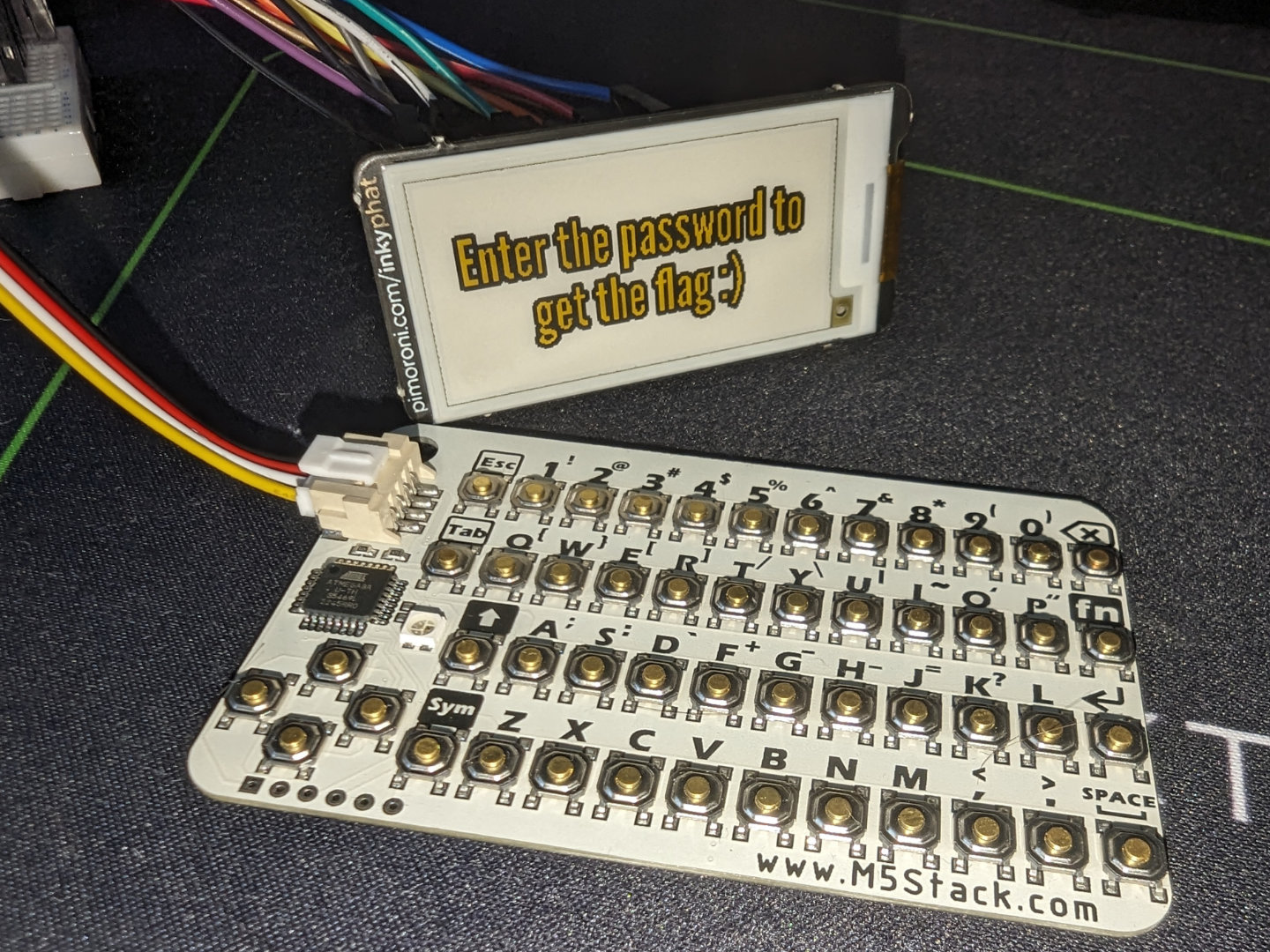
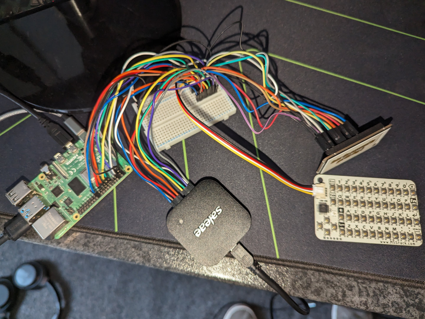
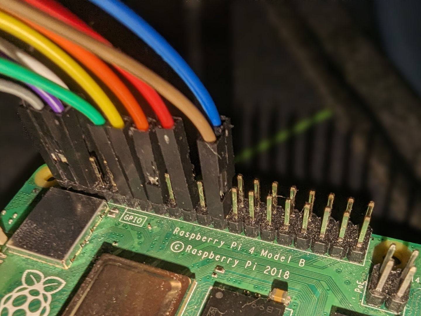
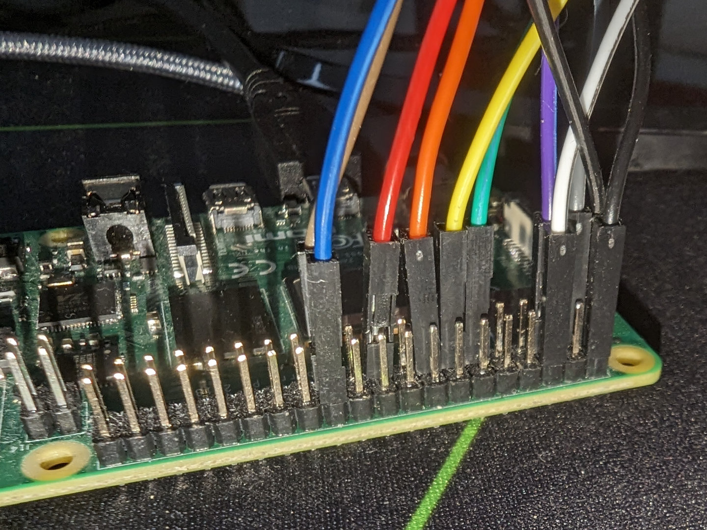
Intro
Instead of sleeping, I made the mistake^Wwise decision of looking at my Discord notification that said there was a hardware challenge in this CTF. It just so happened that there it was using an ATmega-powered keyboard and an e-paper screen, and it almost seemed like a coincidence since I was designing my own keyboard and wanted to interface with an e-paper screen in the near future. This seemed like a great learning opportunity so I started working on the two-part challenge.
There were a few files inside the dist.zip, with the most
interesting one being capture.sal which was technically a zip but actually
the analyzer file for Salae. Sadly it seemed to need their proprietary
program to open.

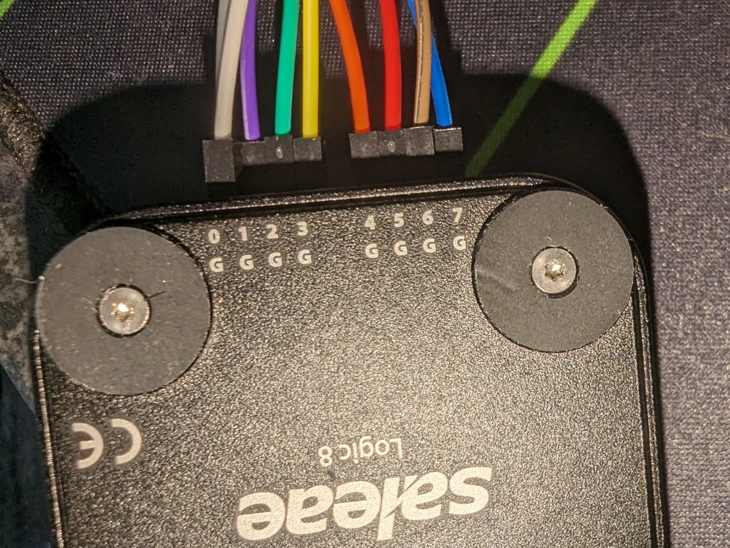
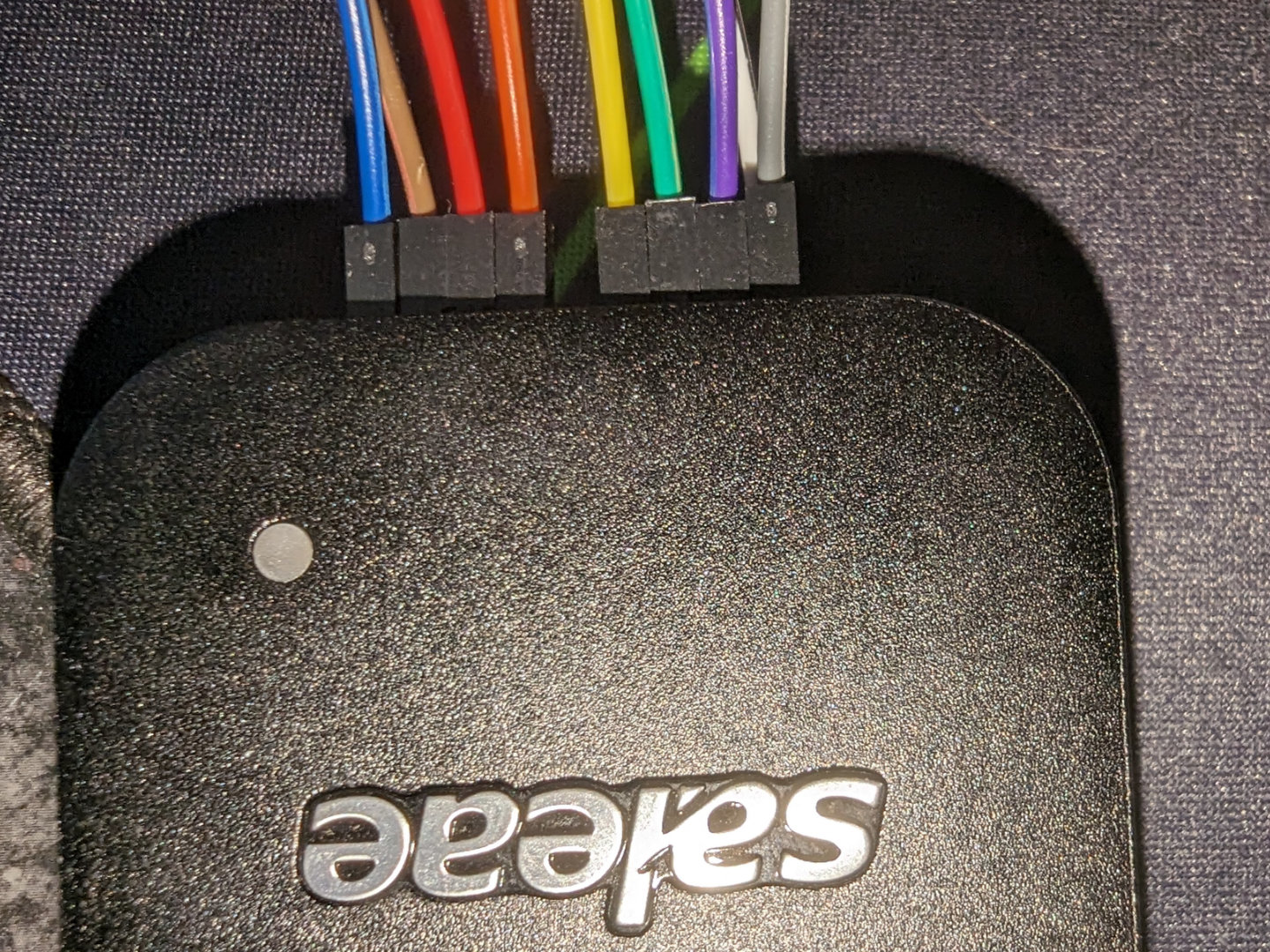
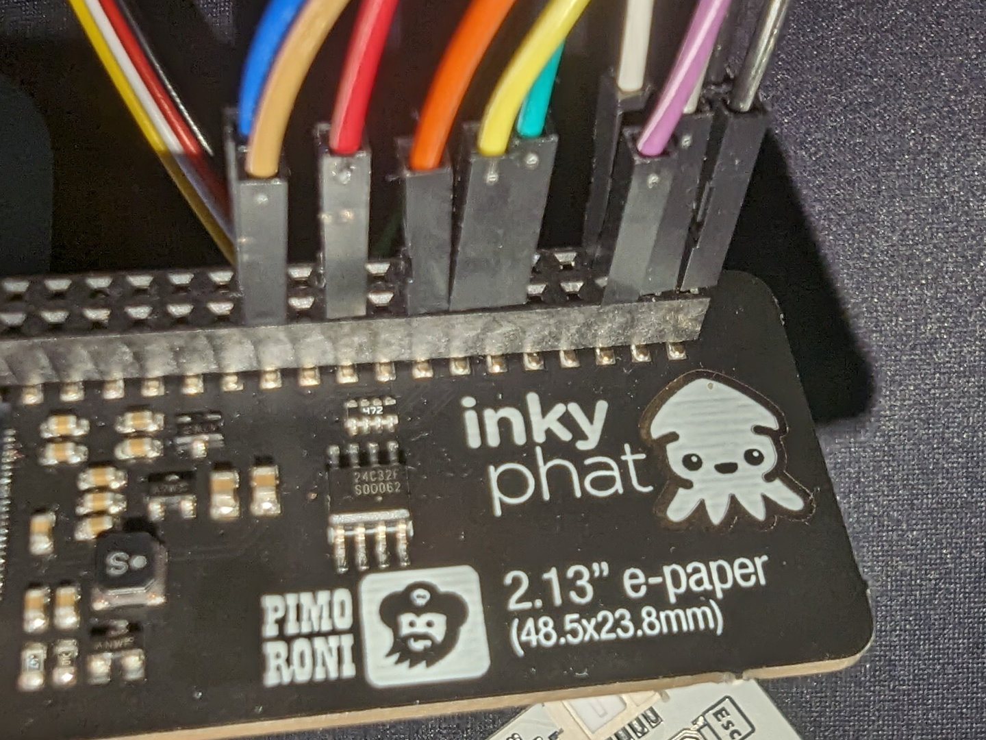
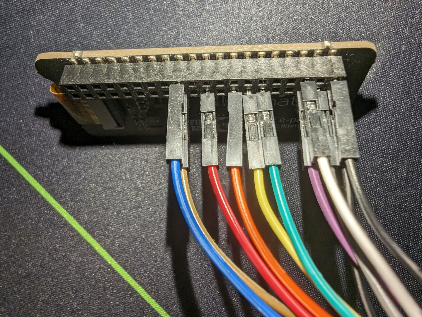
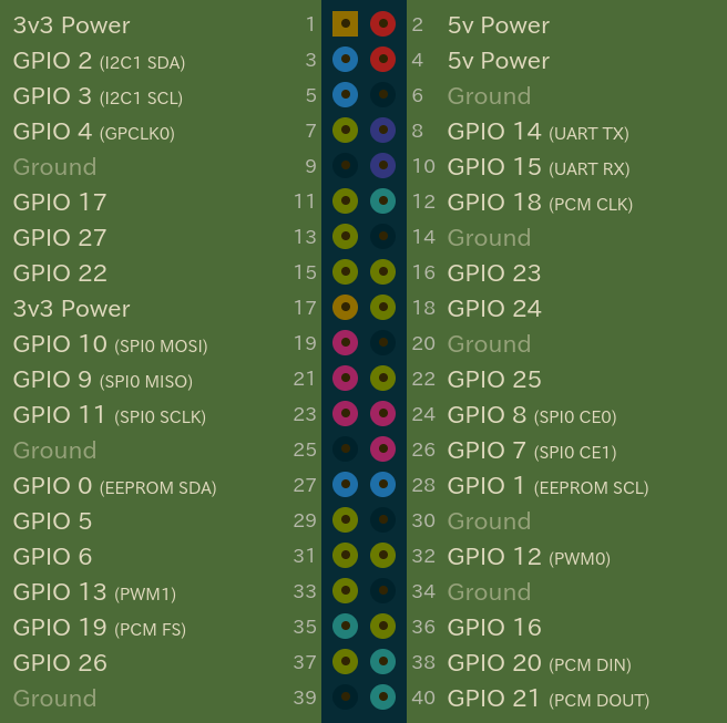
The first thing I did was figuring out what each channel was connected to and what it meant. It seemed that the keyboard and display were controlled by the Raspberry Pi which then seemed to go to the logic analyzer. So I looked at what each channel was connected to and based on its connected pin on the Pi, I found its function via pinout.xyz. I ended up with this:
Channel 0: P03  I2C SDA
Channel 1: P05  I2C SCL
Channel 2: P11  GPIO 17 (busy)
Channel 3: P13  GPIO 27 (reset)
Channel 4: P15  GPIO 22 (data/command)
Channel 5: P21  MOSI
Channel 6: P23  SPI0 SCLK
Channel 7: P24  SPI0 CE0
Part 1
In Logic 2, I opened the I2C analyzer and outputted the dump in the terminal tab into a file
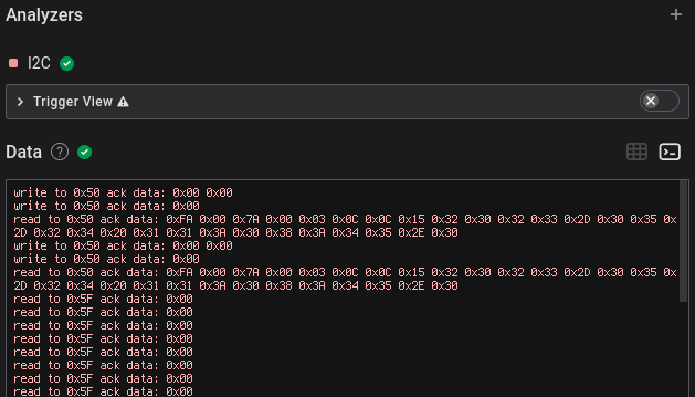
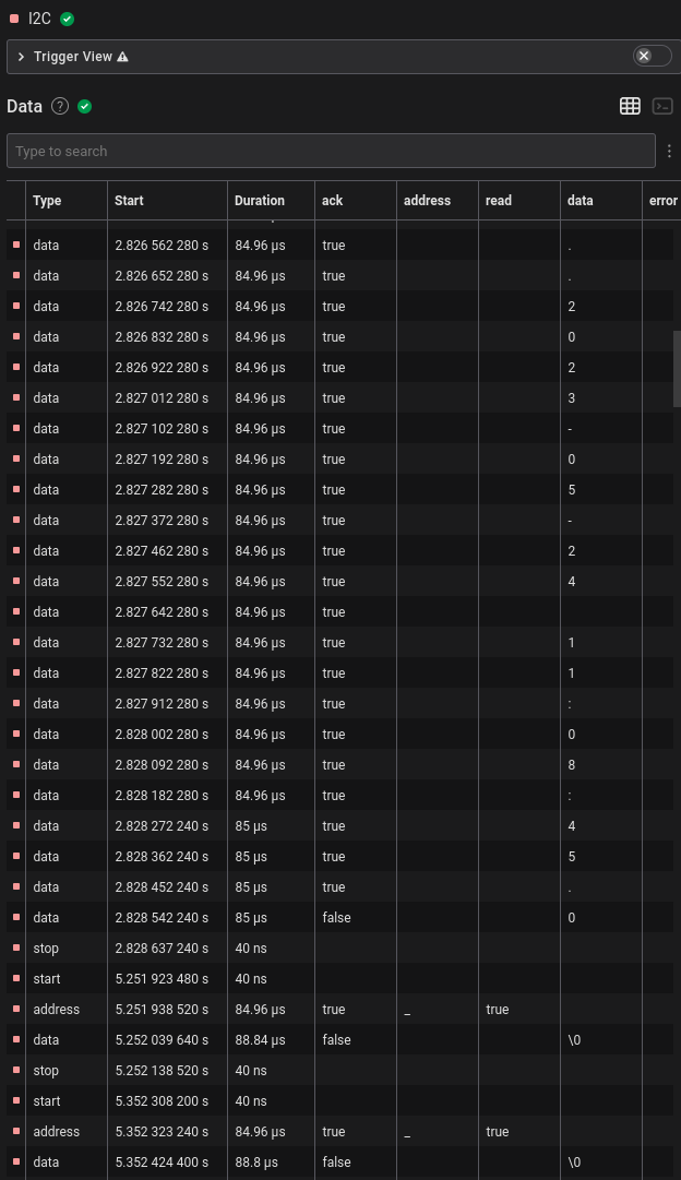 It seemed there was a lot of NUL bytes being sent, probably indicating
that there wasn’t anything during that cycle, and a few seconds later there
were also some other different bytes with NUL and some
 0x01
bytes in between, and these seemed to be printable ASCII.
read to 0x5F ack data: 0x01
read to 0x5F ack data: 0x01
read to 0x5F ack data: 0x66
read to 0x5F ack data: 0x6C
read to 0x5F ack data: 0x61
read to 0x5F ack data: 0x67
read to 0x5F ack data: 0x7B
read to 0x5F ack data: 0x37
read to 0x5F ack data: 0x01
read to 0x5F ack data: 0x31
read to 0x5F ack data: 0x37
read to 0x5F ack data: 0x66
read to 0x5F ack data: 0x37
read to 0x5F ack data: 0x35
read to 0x5F ack data: 0x01
read to 0x5F ack data: 0x33
read to 0x5F ack data: 0x32
read to 0x5F ack data: 0x7D
read to 0x5F ack data: 0x01
read to 0x5F ack data: 0x0D
Filtering out the 0x00 and 0x01 data bytes and
converting to ASCII results in flag{717f7532}.
Part 2
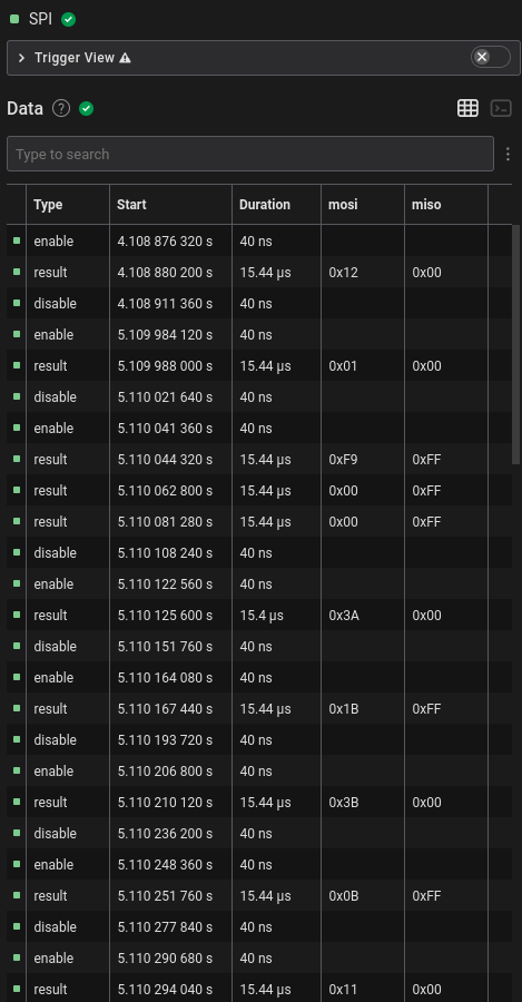
I first outputted the SPI dump from the analyzer into a file and kept only
the MOSI and MISO columns.
Time [s],Packet ID,MOSI,MISO
4.108880200000000,0,0x12,0x00
5.109988000000000,0,0x01,0x00
5.110044320000000,0,0xF9,0xFF
5.110062800000000,0,0x00,0xFF
5.110081280000000,0,0x00,0xFF
5.110125600000000,0,0x3A,0x00
5.110167440000000,0,0x1B,0xFF
5.110210120000000,0,0x3B,0x00
5.110251760000000,0,0x0B,0xFF
To actually understand what’s going on, I couldn’t find any proper documentation initially. There wasn’t even a proper datasheet on DigiKey; the “datasheet” was just a summary of the product.
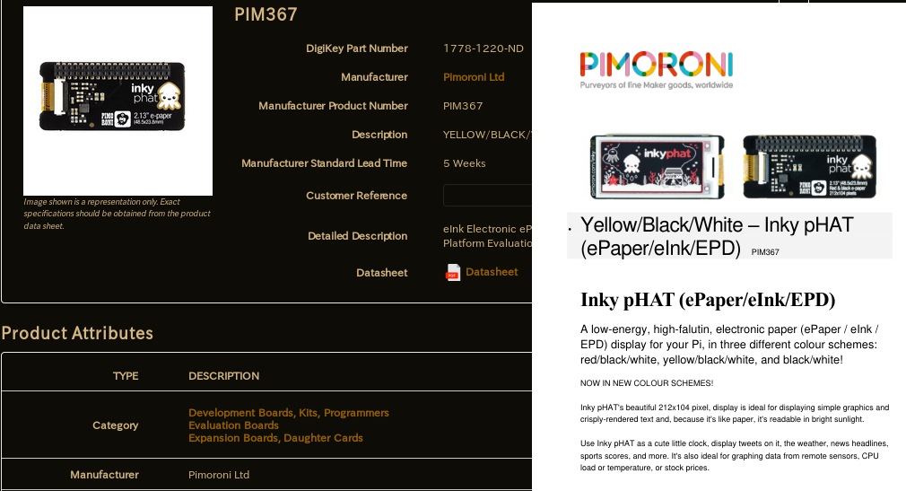
Then I found the Python library source from Pimoroni of their epaper screens, which is probably what was used to make this challenge.
def setup(self):
  """Set up Inky GPIO and reset display."""
  if not self._gpio_setup:
      if self._gpio is None:
          try:
              import RPi.GPIO as GPIO
              self._gpio = GPIO
          except ImportError:
              raise ImportError('This library requires the RPi.GPIO module\nInstall with: sudo apt install python-rpi.gpio')
      self._gpio.setmode(self._gpio.BCM)
      self._gpio.setwarnings(False)
      self._gpio.setup(self.dc_pin, self._gpio.OUT, initial=self._gpio.LOW, pull_up_down=self._gpio.PUD_OFF)
      self._gpio.setup(self.reset_pin, self._gpio.OUT, initial=self._gpio.HIGH, pull_up_down=self._gpio.PUD_OFF)
      self._gpio.setup(self.busy_pin, self._gpio.IN, pull_up_down=self._gpio.PUD_OFF)

      if self._spi_bus is None:
          import spidev
          self._spi_bus = spidev.SpiDev()

      self._spi_bus.open(0, self.cs_pin)
      self._spi_bus.max_speed_hz = 488000

      self._gpio_setup = True

  self._gpio.output(self.reset_pin, self._gpio.LOW)
  time.sleep(0.5)
  self._gpio.output(self.reset_pin, self._gpio.HIGH)
  time.sleep(0.5)

  self._send_command(0x12)  # Soft Reset
  time.sleep(1.0)
  self._busy_wait()

def _update(self, buf_a, buf_b, busy_wait=True):
  """Update display.

  Dispatches display update to correct driver.

  :param buf_a: Black/White pixels
  :param buf_b: Yellow/Red pixels

  """
  self.setup()

  self._send_command(ssd1608.DRIVER_CONTROL, [self.rows - 1, (self.rows - 1) >> 8, 0x00])
  # Set dummy line period
  self._send_command(ssd1608.WRITE_DUMMY, [0x1B])
  # Set Line Width
  self._send_command(ssd1608.WRITE_GATELINE, [0x0B])
  # Data entry squence (scan direction leftward and downward)
  self._send_command(ssd1608.DATA_MODE, [0x03])
  # Set ram X start and end position
  xposBuf = [0x00, self.cols // 8 - 1]
  self._send_command(ssd1608.SET_RAMXPOS, xposBuf)
  # Set ram Y start and end position
  yposBuf = [0x00, 0x00, (self.rows - 1) & 0xFF, (self.rows - 1) >> 8]
  self._send_command(ssd1608.SET_RAMYPOS, yposBuf)
  # VCOM Voltage
  self._send_command(ssd1608.WRITE_VCOM, [0x70])
  # Write LUT DATA
  self._send_command(ssd1608.WRITE_LUT, self._luts[self.lut])

  if self.border_colour == self.BLACK:
      self._send_command(ssd1608.WRITE_BORDER, 0b00000000)
      # GS Transition + Waveform 00 + GSA 0 + GSB 0
  elif self.border_colour == self.RED and self.colour == 'red':
      self._send_command(ssd1608.WRITE_BORDER, 0b00000110)
      # GS Transition + Waveform 01 + GSA 1 + GSB 0
  elif self.border_colour == self.YELLOW and self.colour == 'yellow':
      self._send_command(ssd1608.WRITE_BORDER, 0b00001111)
      # GS Transition + Waveform 11 + GSA 1 + GSB 1
  elif self.border_colour == self.WHITE:
      self._send_command(ssd1608.WRITE_BORDER, 0b00000001)
      # GS Transition + Waveform 00 + GSA 0 + GSB 1

  # Set RAM address to 0, 0
  self._send_command(ssd1608.SET_RAMXCOUNT, [0x00])
  self._send_command(ssd1608.SET_RAMYCOUNT, [0x00, 0x00])

  for data in ((ssd1608.WRITE_RAM, buf_a), (ssd1608.WRITE_ALTRAM, buf_b)):
      cmd, buf = data
      self._send_command(cmd, buf)

  self._busy_wait()
  self._send_command(ssd1608.MASTER_ACTIVATE)
It was also communicating over SPI which seemed to indicate that this was
the proper library. Then I looked at the setup() and
_update() functions in
library/inky/inky_ssd1608.py, and the SPI commands that were
sent in the analyzed dump log matched exactly, including each byte of the LUT
table.
All the SPI commands used in the library are used with named constants
that are defined library/inky/ssd1608.py:
"""Constants for SSD1608 driver IC."""
DRIVER_CONTROL = 0x01
GATE_VOLTAGE = 0x03
SOURCE_VOLTAGE = 0x04
DISPLAY_CONTROL = 0x07
NON_OVERLAP = 0x0B
BOOSTER_SOFT_START = 0x0C
GATE_SCAN_START = 0x0F
DEEP_SLEEP = 0x10
DATA_MODE = 0x11
SW_RESET = 0x12
TEMP_WRITE = 0x1A
TEMP_READ = 0x1B
TEMP_CONTROL = 0x1C
TEMP_LOAD = 0x1D
MASTER_ACTIVATE = 0x20
DISP_CTRL1 = 0x21
DISP_CTRL2 = 0x22
WRITE_RAM = 0x24
WRITE_ALTRAM = 0x26
READ_RAM = 0x25
VCOM_SENSE = 0x28
VCOM_DURATION = 0x29
WRITE_VCOM = 0x2C
READ_OTP = 0x2D
WRITE_LUT = 0x32
WRITE_DUMMY = 0x3A
WRITE_GATELINE = 0x3B
WRITE_BORDER = 0x3C
SET_RAMXPOS = 0x44
SET_RAMYPOS = 0x45
SET_RAMXCOUNT = 0x4E
SET_RAMYCOUNT = 0x4F
NOP = 0xFF
I then noticed that there was a long string of bytes being sent after a
0x24 which in the library indicated that it was the memory
buffer for the black/white channel ending with a 0x00
MISO, with the yellow/red channel afterward with a
0x26 MOSI and also ended with 0x00
MISO
...
0x19,0xFF
0x01,0xFF
0x00,0xFF
0x3C,0x00
0x01,0xFF
0x4E,0x00
0x00,0xFF
0x4F,0x00
0x00,0xFF
0x00,0xFF
0x24,0x00
0xFF,0xFF
0xFF,0xFF
0xFF,0xFF
0xFF,0xFF
0xFF,0xFF
0xFF,0xFF
0xFF,0xFF
0xFF,0xFF
0xFF,0xFF
0xFF,0xFF
...
There also seemed to be two different updates at around 5 seconds and 70 seconds.
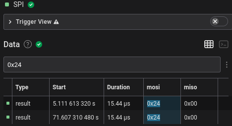
However, the number of bytes written was 4250, which wasn’t the 3812.5 or
2756 bytes I was expecting. This wasn’t divisible by 250 nor 122 and so I was
stuck for a long time. Looking through the library source for more than an
hour with my tired self didn’t help much either. As a last ditch attempt, I
tried converting the raw bytes into an image via Pillow, I used the
L mode (8bpp) and just got an uninteresting garbled
image.

Part 2 Part 2: Electric Boogaloo

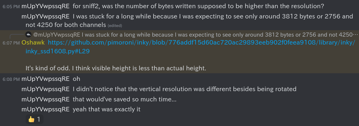
After waking up and working on the CTF after it ended, my partner asked on the Discord and found some interesting very helpful information. It turned out the image was a packed 1bpp image. This meant that each byte in the memory framebuffer contained 8 pixels (8 bits / 1 bits per pixel = 8 pixels).
# under show()
buf_a = numpy.packbits(numpy.where(region == BLACK, 0, 1)).tolist()
buf_b = numpy.packbits(numpy.where(region == RED, 1, 0)).tolist()
In the Python source, this was shown by buf_a and
buf_b being packed bits of 1bpp via NumPy. I don’t know much
about NumPy, so this was a skill issue as I initially assumed it was a
complicated way of saving all the black and red pixels into lists. This is a
good reminder that the documentation should be checked for all unfamiliar
functions instead of naively assuming what they seem to do.
Also in addition to the screen being rotated by 90 degrees, the vertical resolution is actually 136 pixels and not 120 according to the driver.
Knowing all this solved all my problems as 4250 * 8 was indeed divisible by 250 and the actual vertical resolution 136.
All I had to do was change the Pillow mode when converting the bytes to an
image from L (8bpp) to 1 (1bpp) and the (rotated)
resolution from (250, 16) to (136, 250) and got an
actual image.

I used the first updated bytes which was the screen shown in the challenge’s screenshots. Using the second update’s bytes gave half of the flag in the black/white channel and the other half in the yellow/red channel.
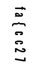
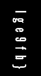
Each character index in both channels seemed to alternate, so the actual
flag was flag{ec9cf2b7}. After I finished writing this writeup
and seeing the two images side-by-side, they probably could’ve been overlayed
after one’s colours are inverted, and is probably what was meant by
“stitching” the channels together.
Conclusion
This was my most favourite CTF challenge by far and I learned a lot, especially about stuff I wanted to learn like how SPI e-paper screens work and not be lost with I2C. I am personally now curious whether the SPI screens can be interfaced directly with the MCU instead of going through an intermediate daughterboard/HAT and how different the protocol for parallel screens are since they’re much faster and use more pins.